

How to Choose a Screen Printing Machine for Membrane Switches ?
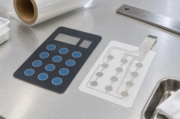
Choose a screen printing machine for membrane switches around the layer you need to print. Define its acceptance tests and the ink’s drying requirements, then trial the film layout and registration method on production material. A graphic overlay and a conductive circuit belong to the same keypad, but their printing requirements differ.
Winshol’s WL-5080DW three-point registration screen printer lists membrane switches among its catalogue applications. It has one printing station and an oven in a roll-fed configuration. For a buying decision, the useful evidence is a sample that has passed through the required prints and the later assembly steps.
Define the printed layer and its acceptance test
Send a layer drawing with the enquiry. Mark which layers the proposed machine will print, which are supplied already printed, and which are cut or assembled elsewhere. Include the finished keypad drawing so the equipment team can see where the printed features must sit after lamination and cutting.
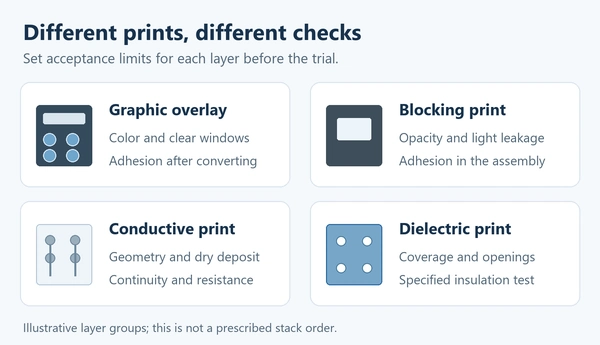
For a graphic overlay, the visible result may depend on color, opacity, clear-window quality and adhesion to the film. If the design is printed on the back of a transparent overlay, state the print side and artwork orientation. A blocking layer may need to stop backlight from showing through an unwanted area. Conductive tracks have another set of requirements: line geometry, continuity and an agreed resistance after the specified drying cycle. The insulating layer needs its own coverage and electrical tests.
| Printed layer | Put this in the machine brief | Check it in the finished sample |
|---|---|---|
| Graphic overlay and legends | Print side, color reference, minimum detail, clear windows and any embossing | Color and opacity, adhesion, window appearance and the result after forming or bonding |
| Opaque or blocking layer | Coverage, registration to the graphics and the intended adhesive contact | Light leakage, layer adhesion and compatibility with the bonded construction |
| Conductive tracks or contact areas | Actual ink, line and gap drawing, target dry deposit and test locations | Continuity, resistance and performance after the design’s specified flex or assembly tests |
| Dielectric or insulating print | Required coverage, openings, ink system and relation to the conductor | Coverage and the insulation or breakdown test defined by the circuit design |
Marabu’s membrane-switch printing guide discusses decorative ink adhesion and compatibility with the film and adhesive. Henkel’s EDAG 820B technical sheet covers a conductive ink, with its own printing, drying and electrical-property information. The sample approval plan needs a test for each layer being printed.
The quotation should show the operations covered by the offered equipment. Punching, adhesive lamination and final functional testing may take place elsewhere. Include those handoffs in the process route so the trial samples can reach the stage at which you will accept them.
Match the film and the usable print format
“PET film” leaves several questions unanswered. Provide the manufacturer and grade, thickness, coating or primer, the printable face and any protective liner. For an overlay, include the surface finish and the areas that must remain transparent. For a circuit layer, identify the film approved for the chosen conductive and dielectric inks.
MacDermid Alpha describes Autostat as a heat-stabilized polyester range for flexible circuitry and membrane-switch layers. Its low-shrink characteristics support dimensional stability during processing. Specify the actual film grade so the trial can establish how your material behaves through repeated printing and drying.
Measure reference distances on the incoming material and again after the proposed drying passes and cooling. Use consistent measurement conditions. Retain samples for embossing or lamination if either operation is part of the job. Production film is needed for approval, even if another grade is used to set up the press.
Next, put the complete layout on the machine drawing. Show the web width, image dimensions, repeat in the feed direction and every registration mark. Leave room for the material handling and later cutting requirements. Our web width versus print area guide explains why the width that passes through a machine and the width that can be printed are separate limits.
The WL-5080DW catalogue lists a maximum web width of 510 mm, a maximum print area of 500 × 800 mm and a maximum feed length of 800 mm. It uses an 800 × 1000 mm screen frame. Have Winshol confirm the artwork orientation and usable margins on your layout. A shop currently printing individual sheets will also need a plan for cutting the printed web and handling it through assembly.
Specify registration against a finished part
Give the supplier a dimensioned drawing with the alignment tolerance attached to named features. The relationship between a legend and a window may need one check, while the relationship between a contact pad and a spacer opening needs another. Identify the reference used by the printing, cutting and assembly stages. Record whether acceptance is measured immediately after printing, after cooling or on the assembled part.
The positioning system must locate the film for each pass. The WL-5080DW is listed as a three-point registration machine. Winshol separately lists the WL-5080CCD with CCD visual registration, right-side feeding and hot-air drying. Compare the proposed configurations on your film, using the intended references and the alignment limits on the drawing.
The product records give no numerical registration guarantee. Obtain measurements at several positions across the layout and along the trial roll. Earlier drying passes may change the film, so the references used for a later print need to remain usable. The site’s CCD versus three-point registration guide covers the comparison in more detail.
If the film’s dimensions change, measure the distances between printed features as well as their position relative to a reference. Locating a mark and maintaining the dimensions across an image are separate checks. Agree on the compensation available in the offered system and verify it after the complete pass sequence.
Select the ink and drying route together
Give the machine supplier the ink technical sheet for each printed layer. The review should cover the specified film, mesh or stencil, deposit, drying or cure process, and time before the next operation. Include the oven specification in the quotation so both suppliers can assess the proposed process.
For decorative layers, Marabu’s guide explains how residual solvent and compatibility between film, ink and adhesive affect later bonding. It also covers UV inks and mixed ink systems. Test the intended layer sequence with the chosen adhesive, including opaque backing and formed areas where present. Assess adhesion on the bonded sample, after any conditioning specified for the job.
Some conductive inks require substantial oven time. Henkel’s EDAG 820B sheet recommends 20 minutes at 120°C and states that insufficient curing can reduce conductivity and adhesion. It also says conditions depend on the application and actual curing equipment. That recommendation applies to EDAG 820B. Set the process for your chosen ink from its current technical sheet and the supplier’s advice.
For a UV dielectric, DuPont’s 5018 technical sheet gives cure conditions alongside flexibility, adhesion and electrical properties, and calls for customers to establish the appropriate cure rate. A hot-air oven and a UV-curing unit perform different processes. Confirm the complete route if both appear in the layer stack.
Winshol’s WL-650-HZL-KX constant-tension oven lists membrane-switch film processing among its applications. Its catalogue gives four heating zones, a maximum temperature of 120°C and 65 m of material storage. If separate drying equipment suits the job, review this oven’s proposed connection to the printer. Usable width and tension range need written confirmation. For drying time, obtain the heated web path and a measured thermal profile; the 65 m storage figure alone cannot establish exposure to the required temperature.
Assess the WL-5080DW against the full pass sequence
The WL-5080DW equipment description lists an unwinding unit, one main printing station, two feeding sections and an oven. A multilayer job needs a plan for additional passes or stations. Count every color and functional print, including backing layers that do not appear in the visible artwork.
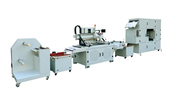
Discuss how material is located again for a later pass, how the previous print contacts rollers or supports, and when the film is ready to rewind or print again. Ask which face is exposed throughout the route. These details matter for overlays with a sensitive front surface and for films carrying previously printed tracks.
Demonstrate minimum printable detail and dry deposit with the proposed ink and screen. Include the finest feature and the heaviest coverage in the trial image. The catalogue’s print area and motor powers provide no line-width or finished circuit-resistance rating; those results need measurement on the sample.
The main machine supply is listed as 220 V. Obtain the oven’s electrical requirements and an installation drawing for the quoted line. Estimate production from a timed job run that includes repeated passes and drying, since the catalogue gives no clear finished-output rating. Report printed film quantities and accepted assembled parts separately.
Run the trial through the next production steps
Bring production film and the intended inks, together with the approved artwork version and layer order. Agree on the measuring instruments, sample locations and pass limits before printing. Keep an untouched material control and record the screen, squeegee settings, web conditions and drying settings used for each pass.
Print the required sequence, then inspect cooled samples at startup, during stable running and later in the roll. Check the different lanes and the edges of the image where applicable. Measure the named registration features after the last drying pass. For the overlay, compare color and opacity under the agreed viewing conditions. Include backlighting if it belongs to the finished specification.
For circuit layers, perform the design’s electrical checks after the required drying and conditioning. Record printed geometry and deposit alongside resistance readings. If a sample fails, those observations help trace the problem to the print, the drying process or the material combination. Apply the resistance limits from this design.
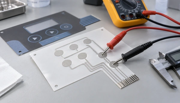
Send representative pieces through the intended cutting, embossing and adhesive-lamination steps. Inspect the bonded construction and perform the agreed switch-function or durability checks on assembled samples where required. Record any defects first found at this stage, and keep the trial settings and approved sample with the quotation.
Report accepted quantities and rejection reasons at the agreed stage, together with setup waste, run length and elapsed time. Use samples throughout the run to judge whether quality holds as production continues. The machine RFQ checklist covers the wider enquiry. For a membrane-switch project, attach the layer drawing, film and ink grades, registration references and finished test plan to the brief sent through Winshol’s contact page.
Common questions
1. What should I specify first when buying a membrane-switch screen printer?
Specify the layer to be printed and its acceptance tests. Add the production film, ink, artwork and pass sequence. Those details determine which registration, printing and drying configuration should be trialed.
2. Can one ink system serve the overlay, conductive circuit and dielectric layer?
Each layer needs an ink suited to its function. Have the ink supplier specify compatible decorative, conductive and insulating products for the actual stack, including the film and adhesive. Approve each printed layer against its own requirements.
3. Is the WL-5080DW a CCD registration machine?
The catalogue identifies it as a three-point registration model. The WL-5080CCD is a separately listed visual-registration configuration. Ask the supplier to demonstrate the proposed method on the job’s references and tolerance.
4. What print format does the WL-5080DW list?
It lists a 500 × 800 mm maximum print area, 510 mm maximum web width and 800 mm maximum feed length, with an 800 × 1000 mm screen frame. Confirm artwork orientation, handling margins and registration marks on a complete layout.
5. Does a single-color machine produce a complete multilayer switch in one pass?
The WL-5080DW has one printing station. A multilayer construction needs an agreed route for additional prints and the later cutting and assembly operations. Ask the quotation to show every pass and the equipment used at each step.
6. What drying temperature should I use for membrane-switch films?
Use the selected ink’s process instructions and the film supplier’s thermal limits. Validate the proposed time and temperature on production material, then check the required adhesion, dimensions and functional properties. There is no single setting for all layer stacks.
7. Does the WL-650-HZL-KX’s 65 m storage establish the drying time?
The catalogue describes material storage length. Obtain the actual heated web path, operating speed and thermal profile to establish exposure. The 120°C maximum rating also needs to be assessed against the ink’s required process.
8. What sample result should I require before approving the machine?
Require samples from the full print sequence on production film, with recorded settings and measurements. Follow them through the next converting or assembly steps, then judge them against the agreed dimensional, visual and functional limits.
