

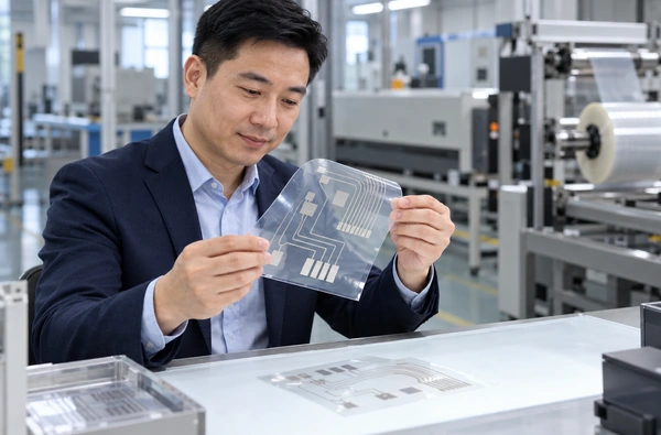
How to Choose a Screen Printing Machine for Flexible Circuits
Choose a screen printing machine for flexible circuits by checking the actual film, conductive ink and complete layer drawing against the proposed equipment. Prove the required line widths, gaps and layer registration on dried samples. Then approve electrical measurements and the specified bending tests on the finished construction before agreeing on accepted production output.
The Winshol WL-5080DW catalogue lists flexible circuits among its applications. It is a single-color, three-point registration screen printer with an included drying oven. Its suitability for a particular circuit needs an artwork and material trial; the catalogue does not state a guaranteed minimum line width or numerical registration accuracy.
This guide focuses on circuits made by printing functional inks onto flexible film. The enquiry should identify the printing stage, protective finishing and connection method so the supplier can define the equipment scope.
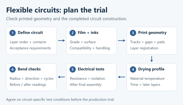
Define the circuit construction and its electrical requirements
Send a drawing that shows every printed layer and the order of production. Identify conductive tracks, contact pads, dielectric areas, crossovers and protective layers where the design uses them. Include the film and any adhesive, liner or laminate that remains in the finished part.
For a material example, Henkel describes EDAG 418SS as a screen-printable silver ink for low-voltage circuitry on flexible substrates and for crossovers over compatible UV-curable dielectric inks. The selected conductor and dielectric still need approval together for the intended construction. The ink description does not establish the capability of a particular press.
Mark the connection points and identify which circuit paths will be measured. Include allowable path resistance, continuity requirements and isolation between specified conductors, with the measurement conditions. A netlist or equivalent connection drawing helps the supplier understand which pads must connect and which must remain isolated.
Also describe how the circuit will move in service. It may be bent once during assembly, held at a fixed curve, or flexed repeatedly. State the required bend geometry and service conditions. If the application also requires stretching, include that requirement separately in the material review.
Set the trial endpoint in the enquiry: dried printed web, protected circuit, or connected assembly. The quotation should identify responsibility for cutting, connector attachment and functional testing, including the operations the buyer will carry out after printing.
Specify the film and check its path through the equipment
The material brief should name the film manufacturer and grade, thickness, printable side and surface treatment. Add the actual roll width, core size, outside diameter and winding orientation. Supply enough production-grade material for setup and the agreed trial run.
For coated or multilayer film, show which surface meets the screen and which surfaces touch the machine. Review the unwinder, printing support, drying path and take-up arrangement. Previous printed layers may contact rollers during a later pass, so include those contact points in the handling review.
Inspect trial material for scratches, creases, surface pickup and winding marks. Include the intended holding period between layers if the process stores intermediate rolls. Record the winding and storage conditions for those samples; damage introduced between print passes can otherwise be difficult to trace.
Measure dimensional change through the proposed drying sequence. Use identified reference positions and measure after the agreed cooling and conditioning period. If a pre-shrink operation is being considered, compare treated and untreated film through the later process. The result should show whether the treatment helps meet the drawing requirements.
Sheet-format samples can help with inspection. For a WL-5080DW production enquiry, include the roll specification as well. A process developed on individual sheets needs a feeding and handling review for this roll-fed configuration.
Prove the required line geometry and layer registration
WL-5080DW has a listed maximum print area of 500 × 800 mm, maximum web width of 510 mm, maximum feed length of 800 mm, and screen frame size of 800 × 1000 mm. Check the complete production layout against these separate dimensions. Our web width versus print area guide explains how to review the print envelope and material margins.
The layout should include connection pads, registration references, inspection coupons and cutting allowance as well as the circuit itself. Label the feed direction. Confirm how many circuits fit in one repeat and whether every feature can be printed and inspected in that arrangement.
Use the production artwork for detail trials. Include narrow tracks, closely spaced conductors, changes in direction and pad-to-track transitions at their actual scale. With the proposed ink and screen setup, measure the dried line widths, clear gaps and specified coating thickness.
Inspect for breaks, bridged gaps, pinholes and irregular edges at the agreed magnification. Look closely at the demanding features identified for the trial, even when the overall dimensions are correct. Record their measurements at identified positions across the web and along the run.
The catalogue identifies three-point registration for WL-5080DW. Ask the supplier to demonstrate the proposed references using the actual film and layer sequence. The allowed positional error should be defined at features such as dielectric openings, crossovers and connection pads, then checked after the relevant drying and cooling stages.
WL-5080DW is not identified as a CCD configuration. A camera-based requirement needs a separately confirmed machine configuration and trial using the same artwork and acceptance limits.
Review the printer and ovens by their process roles
Use the product records to identify the printing, pre-treatment and drying stages that need review. The following equipment listings are separate configurations; their inclusion in one enquiry requires an integration assessment.
| Winshol configuration | Relevant catalogue information | Confirm for the proposed circuit |
|---|---|---|
| WL-5080DW screen printer | Single color; three-point registration; 500 × 800 mm maximum print area; 510 mm maximum web width; included drying oven | Actual detail reproduction; layer/pass sequence; registration result; included oven specification and complete equipment scope |
| WL-500-YSS-KX pre-shrink oven | 500 mm maximum web width; four heating zones; 60 m listed material storage | Working temperature range; usable material path; dimensional result after treatment and later printing |
| WL-650-HZL-KX constant-tension oven | Maximum temperature 120°C; four heating zones; 65 m listed material storage | Usable web width; tension range; effective heated path; drying profile on the actual film |
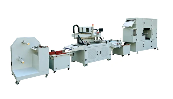
The printer’s 510 mm maximum web width exceeds the pre-shrink oven’s listed 500 mm limit. Resolve that difference using the actual production web before proposing the two together. WL-650-HZL-KX needs written width confirmation; its model number does not establish a 650 mm usable width.
The pre-shrink oven’s working temperature range is unconfirmed in the project record. WL-5080DW’s included oven is also not identified as either standalone oven in the table. Request the exact dryer supplied with the printer and identify any additional treatment stage separately on the quotation.
A circuit with conductor, dielectric and another conductor layer needs a reviewed sequence of printing and drying operations. WL-5080DW’s single-color listing requires the supplier to specify separate passes or another proposed arrangement for multiple inks. Include screen changes, return feeding and handling of the intermediate rolls.
For the constant-tension oven, obtain the quoted tension range and review material behavior under heat. The integration drawing should show web transfer between machines and identify motion and control responsibilities.
Match each ink to a demonstrated drying profile
Collect the current technical and safety data sheets for each proposed ink. The layer schedule should show its drying or curing method, required exposure and limits for the underlying film and previous layers. Include protective finishing if it adds another thermal or UV operation.
Henkel’s April 2025 ECI 1010 data sheet gives a recommended drying cycle of 15 minutes at 120°C for this screen-printable silver ink. It also says the conditions depend on the application, equipment loading and actual oven temperatures. Source: Henkel ECI 1010.
WL-650-HZL-KX lists a maximum temperature of 120°C. Matching that number to the ink’s guideline is only an initial temperature check. The proposed configuration must demonstrate the required exposure, material temperature and uniformity under the trial loading. Review the available operating margin with the equipment and ink suppliers before accepting the process.
The listed 60 m and 65 m storage lengths do not establish drying time. Obtain the internal threading diagram and identify the effective heated sections, then use the proposed operating motion to determine exposure. Include heat-up and cooling; the controller setpoint alone does not describe the printed layer’s thermal history.
During the trial, record zone settings, measured material temperature, running conditions and loading. Recheck electrical and dimensional results after subsequent layers have passed through their own process. The completed layer stack needs an accepted recipe as well as the first printed layer.
If a dielectric uses UV curing, identify the required UV equipment separately. The catalogue’s oven descriptions do not specify UV capability. Our UV curing versus hot-air drying guide provides a broader comparison for the enquiry.
Agree on electrical, isolation and bending tests
Before printing, agree on a sample plan using the production artwork and selected materials. Each sample needs an identifiable reel position, across-web location and process record. The plan should name the measurement equipment, acceptance limits and who performs the tests after printing.
Measure circuit-path resistance consistently
Record the selected paths, probe locations, sample condition and instrument settings. A continuity check can identify an open path, while a measured resistance value allows comparison against the drawing requirement. Include the contact arrangement so results from different laboratories can be compared.
For low-resistance paths, assess whether a four-wire method is needed. Tektronix explains that a two-wire measurement includes test-lead resistance, while a Kelvin connection uses separate current and voltage-sensing leads to reduce that error. Its guidance also discusses device heating. Choose test conditions suitable for the printed circuit and record them with the result.
Keep ink sheet resistance and circuit-path resistance separate in the acceptance document. A material value reported in ohms per square under defined coating conditions cannot directly replace the requirement between two circuit pads. Use material coupons for process monitoring where appropriate and measure the specified paths on the actual circuit.
Check isolation and the finished connection areas
Inspect close conductor gaps and dielectric coverage against the drawing. Define which isolated nets or crossover areas require electrical testing, with the method, test conditions and allowable result set by the circuit designer. A photograph of a clear gap is insufficient evidence of the specified electrical isolation.
Evaluate the intended connection method on representative samples. For a connector, conductive adhesive or other specified attachment, record the pad finish and assembly process. Recheck the relevant paths after attachment and protective finishing, and inspect the connection area for damage or unwanted coverage.
Test the required bending behavior
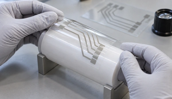
Specify bend radius, direction, location and cycle count from the application requirements. State whether the test calls for measurements during movement, after the sample returns flat, or both. Include the intended laminate and connector support when they are part of the service construction.
Henkel’s ECI 1010 data sheet reports a resistance change after a double-crease test. This illustrates the need to state the mechanical test and its electrical result together; it does not establish repeated-flex life for a customer’s circuit. Source: Henkel ECI 1010.
| Sample stage | Agreed checks | Result to retain |
|---|---|---|
| Dried conductor layer | Line geometry, defects, thickness and selected path resistance | Measurements linked to the print and drying settings |
| Subsequent printed layers | Layer registration, conductor clearances and dielectric coverage | Feature-level inspection and the specified isolation results |
| Connected and protected circuit | Connection quality, path resistance and required functional checks | Assembly revision and electrical measurements |
| Bent or flexed construction | Defined bend conditions, visual damage and electrical change | Before/after readings or monitored results, as required |
| Production trial samples | Results across the web and along the agreed run | Distribution of accepted and rejected samples, with recorded causes |
Retain representative samples with their process records, and report the spread of measured results against the agreed limits. Where durability testing takes place after the equipment trial, state who performs it and how the result affects final approval.
Estimate capacity using the complete production sequence
Specify whether output means printed repeats, protected circuit pieces or connected assemblies. Include the number of circuits per repeat, required layers and typical batch size. This gives the supplier a common basis for the estimate.
The production calculation should use trial-approved printing and drying conditions. Include return passes, screen changes, cooling, reel changes and expected setup waste. For each ink change, clarify whether the estimate includes cleaning, setup and the checks needed before accepted production resumes.
During the agreed trial period, count output that meets the acceptance requirements. For a job with several printing and drying stages, request an estimate through the last operation included in the quotation. The supplier should show the timing and yield assumptions behind that estimate.
The enquiry package should contain:
- Production film and roll specification, with representative material.
- Artwork revision, full repeat layout and layer sequence.
- Ink technical and safety data sheets, including drying requirements.
- Line geometry, registration and electrical acceptance requirements.
- Connection method and the required bending or service tests.
- Output unit, batch sizes, available space and site services.
WL-5080DW lists a 220 V main machine supply. WL-500-YSS-KX and WL-650-HZL-KX list 380 V supplies and powers of 28 kW and 23 kW respectively. Request the complete electrical schedule and installation drawing for the quoted arrangement, including auxiliaries, extraction and access for threading and reel handling.
Use our screen printing machine RFQ checklist to organize the technical package and sample-approval responsibilities.
Frequently asked questions
1. Can WL-5080DW print flexible circuits?
Flexible circuits are a catalogue-listed application. The model is a roll-fed, single-color screen printer with three-point registration and an included drying oven. Approve the actual circuit through an artwork and material trial, including the specified electrical and mechanical checks.
2. What is the minimum printable line width?
The available catalogue record does not give a guaranteed minimum. Send the required tracks, gaps and transitions at production scale. Ask the supplier to measure the dried features using the proposed ink and screen setup before agreeing on a capability requirement.
3. Can one pass print a multilayer circuit?
WL-5080DW is listed as single color. Provide the layer schedule so the supplier can define the required passes, drying stages, screen changes and return-registration procedure. Any different production arrangement needs a confirmed configuration.
4. Is three-point registration the same as CCD registration?
No. The catalogue identifies three-point registration for WL-5080DW. A camera-based requirement needs separate confirmation. Specify the actual features and positional tolerances for the trial.
5. Does the film always need pre-shrink treatment?
The decision depends on dimensional change through the intended process. Compare untreated and treated material after the complete thermal sequence and agreed conditioning. Select treatment settings from the trial result and material requirements.
6. Does a 120°C oven rating prove ink compatibility?
It establishes a listed temperature ceiling. Compatibility also requires the specified material temperature, exposure and drying method under the proposed loading. Confirm the actual dryer configuration and validate the finished circuit results.
7. Can a continuity test replace resistance and isolation measurements?
Continuity is one check. The acceptance document should also define path resistance and any required isolation tests, with their measurement conditions. Use the circuit’s electrical requirements to select the tests.
8. What should a flexible-circuit trial report include?
Include material batches, artwork revision, layer order, printing and drying settings, sample locations and the agreed inspection results. Add connection and bending-test results when they are in scope. Record both accepted and rejected samples so the approval reflects the agreed run.
Review your flexible-circuit project with Winshol
Contact Winshol with the film specification, complete circuit drawing and sample-acceptance requirements. Review the WL-5080DW configuration alongside the printing passes, drying arrangement and handling interfaces the materials need. Use the trial’s recorded geometry and electrical results to set acceptance conditions in the quotation.